Drawing Assignment Instructions
Plans, Sections, and Elevations are the most basic drawings for studying buildings, giving clear primary information about the nature of the building.
Plans indicate the layout and flow of space at a particular level of the building.

Plan views are also useful for diagramming the overall ordering system of a building.

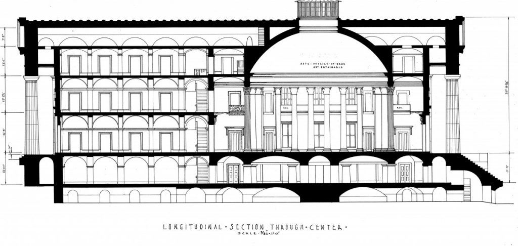
Building sections are critical drawings for understanding the relationship between space, structure, and building form. Structural configuration and thickness at exterior walls, floors, and roofs is a critical aspect of the information these drawings provide.
Elevations are constructed using sections as guides and sources of projection of critical elements in the correct position.

These drawings must be coordinated carefully with each other, and developed with clear reference lines (structural grid lines and key elevation/level lines).
Assignment Context:
This assignment builds on the knowledge and experience of careful documentation and coordinated drawing development from ARCH 1101. This assignment also offers documentation of masonry architectural elements.
Prerequisites:
Understanding of orthographic projection and detailed observation of case study details.
Recommended Text:
Ching, Francis. Architecture Graphics. John Wiley and Sons, 2009.
Plagiarism:
Student work submitted must be original and developed individually. Tracing is not acceptable. All construction lines and notations during drawing construction are to remain visible at final submission. Drawings without construction lines (guidelines) will be downgrading significantly.
Learning Outcomes
| Learning Outcomes | Assessment Methods |
| Upon successful completion of this assignment the student shall be able to: | To evaluate the students’ achievement of the learning objectives, the professor will do the following: |
| Develop coordinated, accurate, and consistent set of two -dimensional drawings documenting the building section and elevation | Review student drawing set for consistency, orthographic projection and coordination between drawings, and dimensional accuracy. |
| Understand the construction of building sections and elevations following drawing conventions and the critical application of reference lines | Review student drawing set submission for careful documentation and application of structural grid and elevation lines as well as line weights. |
Instructions
NOTE: All drawings to be 1/16″=1′-0″ , 3/32″=1′-0″, or 1/8″=1′-0″.
Your drawing paper should be large enough to fit your drawings. 12″x 18″ sheets are suggested unless otherwise agreed with your professor.
Drawing Due for Module 1:
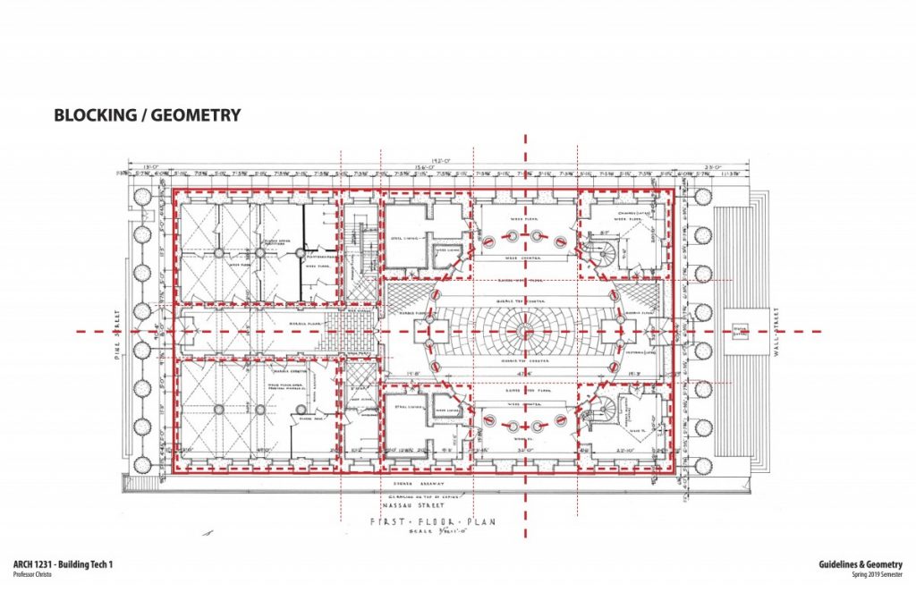
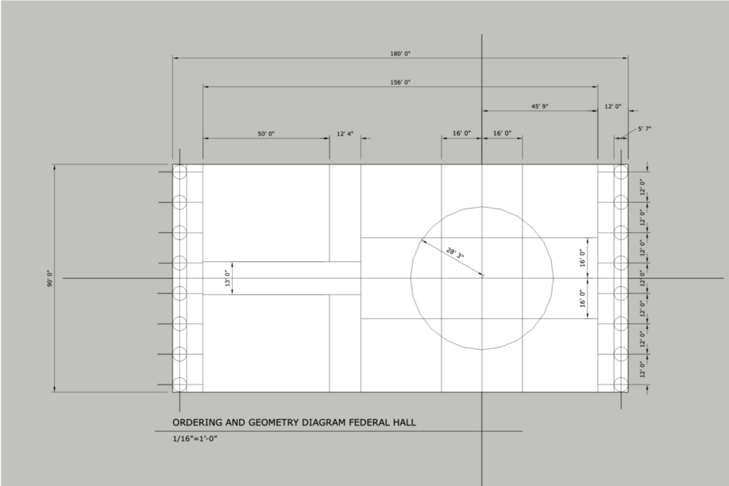
- Federal Hall First Floor Diagram Study
- Federal Hall First Floor Plan
- Federal Hall Longitudinal Section
- Federal Hall South Elevation
Follow these steps:
- Develop Diagram of Building Order, Geometry, Grid, Symmetry, and Spatial Zoning
- Using Trace Paper Overlay technique, Layout Out First Floor Plan of Federal Hall
- Using Trace Paper Overlay technique, Develop Longitudinal Building Section
- Using Trace Paper Overlay technique, Develop South Elevation
- Complete each of these drawings. Scan on flatbed scanner or with an App using your camera. CamScanner (CS) is a good app to try. Name and format per the course formatting guidelines.
- Submit all formatted drawings to the Dropbox folder.


Leave a Reply